An online project under the direction of the CAPE ANN MUSEUM
Historical Materials: Maritime & Other Industries & Facilities
Historical Materials » Maritime & Other Industries & Facilities » Marine Railways
You have navigated to this pages from catalog entry: Three Master on the Gloucester Railways, 1857 (inv. 29)
Marine Railways
View related Fitz Henry Lane catalog entries (3) »
A marine railway is a service facility for hauling ships out of the water to repair and clean the hulls. They are not used for shipbuilding, although some of the work done on them may call for the services of skilled ship carpenters.
Every marine railway in Gloucester had the following basic features:
1. The hauling ways – a straight, gently-inclined slope to convey a ship from deep water to dry ground.
2. Iron rails in pairs – two pairs of rails on the rail beams and two corresponding pairs on the underside of the hauling cradle.
3. A hauling cradle which carries and supports the ship.
4. Two racks of rollers which travel on the rails as the cradle travels over them. The principle is that of roller bearings.
5. A hauling chain and machinery to pull the cradle up the ways. Prior to steam-powered hauling winches, capstans with reduction gears, turned by horses, were used. This may have been the case with the first of the two railways built by Parker Burnham & Bros.
The lengths of the Burnham hauling ways were approximately 250 feet (first railway) to 350 feet (second railway) with an average rise of one foot in fifteen feet. Ideally, the slope should be perfectly straight, but the Gloucester ways usually had some unwanted “crown” which made hauling more difficult. While the railways in Rocky Neck were built on a jutting rise of land, the railways at Duncan’s point were built in hollows, as those locations offered the straightest inclines.
As a foundation for the rails, pairs of heavy spiles (wood pilings), set twelve feet apart, were driven every twelve feet down to bedrock. They were capped with cross-timbers which resembled railroad ties, but were much heavier. Over the cross-timbers, a pair of bed timbers was laid the length of the ways. Cross-timbers were fastened to the spiles with long iron spikes. The bed timbers were spiked down to the cross timbers in the same fashion.
Pairs of iron rails were spiked down to the bed timbers, with great care taken that they were spaced uniformly and that no spikes protruded to interfere with the rollers. The rails were plain iron bar stock, two inches by three inches in cross-section, and bored to take the spikes. Locomotive rails were not used.
Riding on each pair of rails was a rack made of fourteen oak frames, each sixteen feet long and fitted with eighteen cast iron rollers. For a railway 350 feet long,a 224-foot rack (fourteen frame units long, totaling 28 frames and 504 rollers) was needed to allow a 100-foot cradle to travel from the low end of the way to the upper end. Although cumbersome, rollers were durable and the racks were easy to repair.
The cradle was a wooden frame with iron rails on its underside which corresponded to those on the rail bed timbers. Its dual purpose was to raise the ship by traversing the racks and to support the hull safely while the repair crews were working on it.
The base of the cradle consisted of two “fore-and-afters” with the rails on their bottom sides. Over them were heavy cross-pieces of alternating 14-foot and 24-foot lengths, spaced every five feet. On the centers of the cross-pieces were the keel blocks – short lengths of hardwood which supported the hull along the keel. On the outboard ends of three long cross-pieces were adjustable bilge blocks which moved laterally on wooden tracks. They supported the hull at its bilges so it could not tip over.
Each vessel to be hauled had a different shape to its keel and bilges, so for each hauling the keel blocks and bilge blocks were specially built up so the hull would rest on all of them, distributing its weight as evenly as possible. Hull bottom plans or tables of bottom dimensions were kept on file in the railway office for future reference.
Hauling a Ship
To get a ship on a cradle, the cradle had to be hauled out to the lower end of the hauling ways so the hull could be positioned over it. The cradle, being made of wood, had to be ballasted so it would not float off the rails. Stone blocks were the usual ballast in that period. All keel and bilge blocks were securely nailed to the cradle frame or to the sliding bases of the bilge blocks.
The vessel was carefully positioned and centered over the submerged cradle, then both were hauled in together, the cradle rising until the keel rested firmly on it. The bilge blocks were then hauled inboard (toward the keel), using ropes, until they rested firmly under the bilges. The cradle could then be hauled out with the vessel safely on it.
Hauling a ship was not without risks, and if the hull was not correctly centered over the cradle, or of the keel- or bilge blocks were not properly in place, there was danger of accidents or damage. In the worst case, a ship could “fall down” on the cradle, or sometimes off it, causing great damage to the vessel, the rails and cradle, and adjoining wharves. Then there was the expense of pulling the vessel off the ways so it could be hauled again.
Hauling the cradle was done with chain, which was taken around a type of iron capstan called a “wildcat”, turned by reduction gears connected to the power source. In its earliest years, the Burnham railway probably used horses, harnessed to a second capstan which turned the wildcat. This soon gave way to steam power, as evidenced in Lane’s 1857 painting of the Burnham railway and his 1859 lithograph of Gloucester Harbor. The inhaul chain was made of long, heavy links shackled to an iron towing bar at the “bow end” of the cradle. A smaller outhaul chain, shackled to the cradle’s “stern end”, ran out to an iron capstan at the deep end of the railway and back to the hauling machinery, where it was connected to the inhaul chain. A wooden trough was laid over the cross timbers to reduce chafing from the chains as they traveled over them.
Since the early 1850s, steam engines powered the marine railways in Gloucester, and were not replaced by gasoline or diesel engines until the 1920s or ‘30s. A machinery building at the head of the larger of Burnham’s railways in Three Master on the Gloucester Railways, 1857 (inv. 29) is obscured by the ship on the cradle, but the conspicuous smokestack leaves no doubt about the presence of steam power.
The ground level of the machinery building was occupied by a steam boiler, an engine, and reduction gears linked to the capstan. An attached workshop was equipped with a power saw, lathe, and hand tools for most types of vessel repair work and engine maintenance. On one side of the foundation would be a roofed coal bin, while on another side would be a wooden steam box for the steam-bending of replacement planking for vessels under repair.
Over the machinery level was a floor used for offices and repair records. The roof was fitted with a skylight aligned exactly with the center line of the hauling way. An observer from this level could tell very accurately if a vessel being hauled was positioned over the cradle’s center line.
Erik Ronnberg
Reference: This information was compiled in 1991 from interviews by the author with the late Joseph Santapaola of Gloucester, who was employed by, and later managed, the marine railways in Gloucester over sixty years, starting early in the 20th century. The data was used for a reconstruction of the marine railways in the diorama exhibited at the Columbian Exposition at Chicago in 1893, now on exhibit at the Cape Ann Museum. The resulting diorama agrees closely in detail with photographs of the actual facilities dating from the 1880s, as well as many details in Lane’s painting of 1857 (Three Master on the Gloucester Railways, 1857 (inv. 29)).
Related tables: Burnham Brothers Marine Railway » // Graving Beach »
Wood rails, metal rollers, chain; wood cradle. Scale: ½" = 1' (1:24)
Original diorama components made, 1892; replacements made, 1993.
Cape Ann Museum, from Gloucester Chamber of Commerce, 1925 (2014.071)
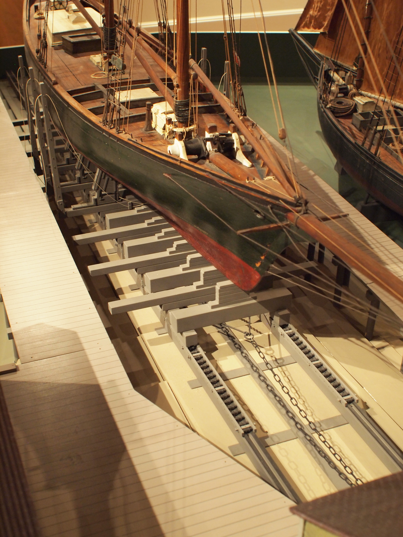
A schooner is shown hauled out on a cradle which travels over racks of rollers on a wood and metal track.
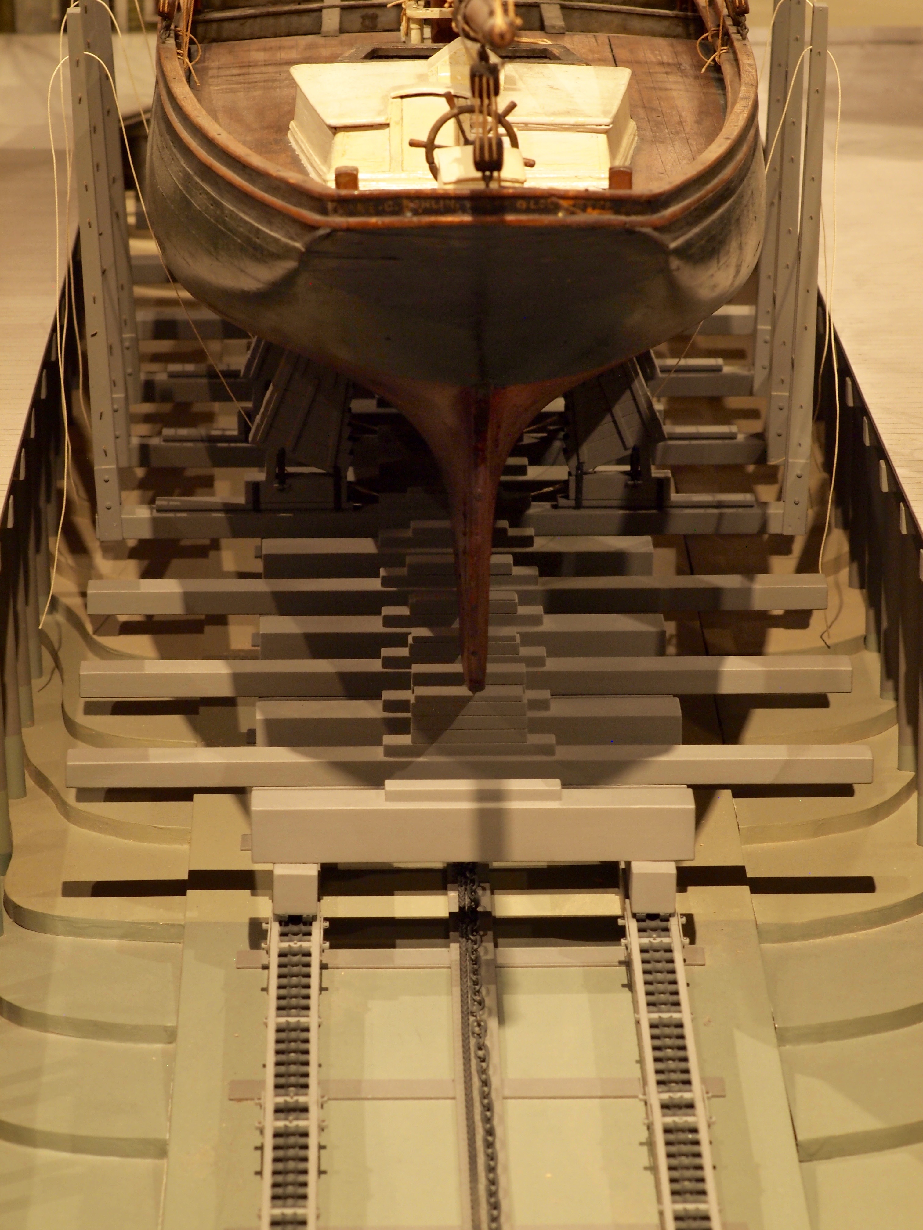
Wood rails, metal rollers, chain; wood cradle. Scale: ½" = 1' (1:24)
Original diorama components made, 1892; replacements made, 1993.
Cape Ann Museum, from Gloucester Chamber of Commerce, 1925 (2014.071)
Close up showing detail of rollers and hauling chain.
Also filed under: Burnham Brothers Marine Railway »
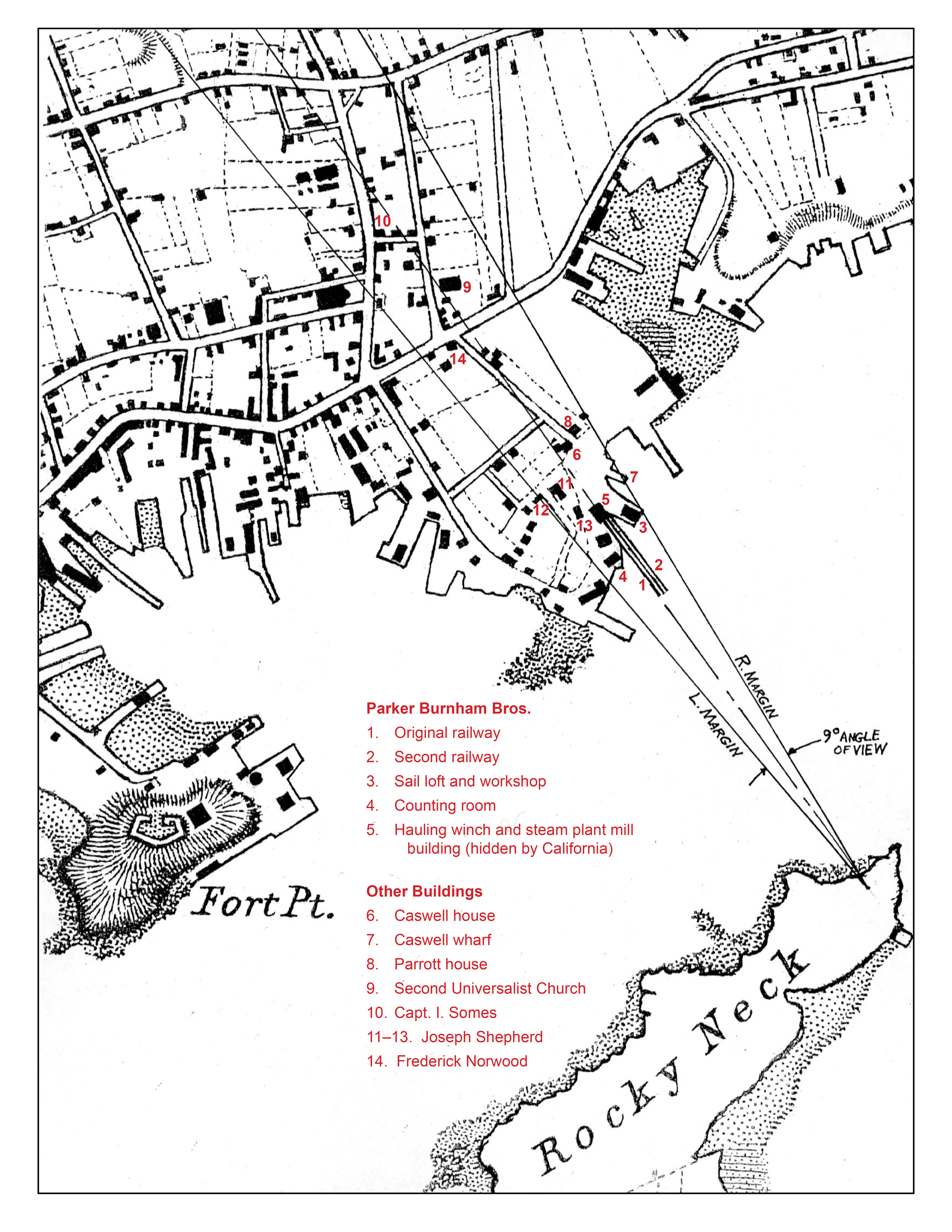
44 x 34 in.
John Hanson, Publisher
Cape Ann Museum Library & Archive
Also filed under: Burnham Brothers Marine Railway »
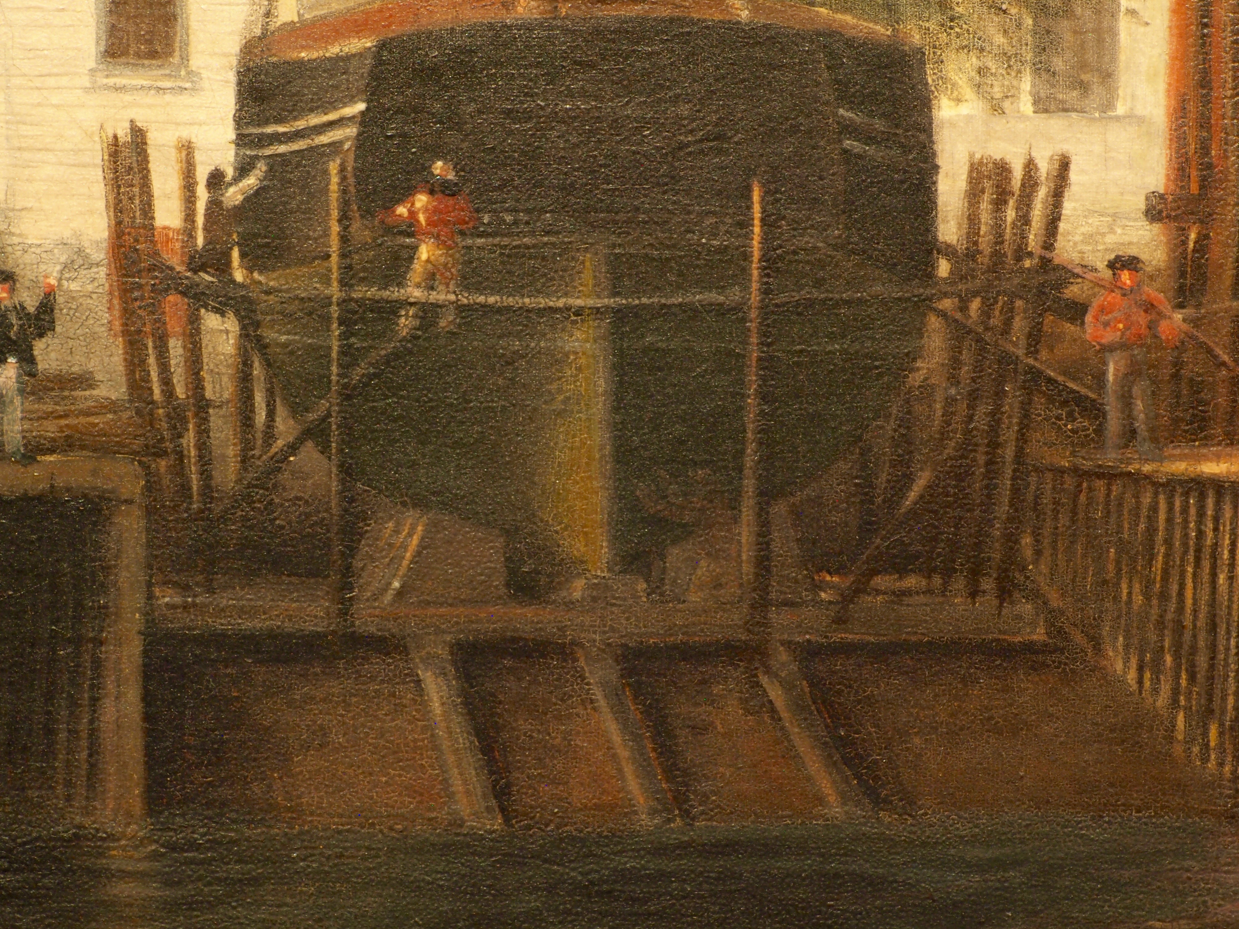
Oil on canvas
39 1/4 x 59 1/4 in.
Detail showing construction of marine railway. Details of the rollers and chain are obscured due to past cleaning efforts.
Also filed under: Burnham Brothers Marine Railway »